LIS3DSH Sensor Block Description
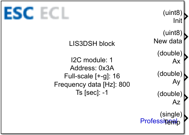
This block supports LIS3DSH sensor on STM microcontrollers. LIS3DSH is a 3-axis MEMS accelerometer that can be used to measure acceleration along three axes (X, Y, Z) and temperature. This block allows reading data from the sensor using either I2C or SPI interfaces, enabling integration with various STM32 microcontroller models.
Contents
Inputs
This block does not have any inputs.
Outputs
| Output Name | Type | Description |
|---|---|---|
| Init | uint8 | Initialization status of the LIS3DSH sensor. Returns1 for successful initialization0 (or an error code) if the setup failed. |
| New data | uint8 | Data ready flag:1 - new data is ready to read0 - data is not ready to read / read error |
| Ax | double | Measured acceleration along the X-axis, scaled according to the selected full-scale configuration. |
| Ay | double | Measured acceleration along the Y-axis, scaled according to the selected full-scale configuration. |
| Az | double | Measured acceleration along the Z-axis, scaled according to the selected full-scale configuration. |
| Temp | single | Conditional output Temperature reading from the sensor’s internal temperature sensor. Note: This output is exposed only when the Read parameter is configured to Akclereometer + Temperature. |
Block parameters for I2C and SPI
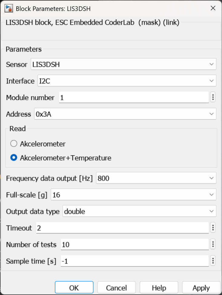
Block parameters for I2C
| Parameter | Description |
|---|---|
| Sensor | Switch between available sensors |
| Interface | Switch between interfaces:I2C - select I2C interfaceSPI - select SPI interface |
| Module number | Number of I2C/SPI module used in the model |
| Address | Address of the slave motion sensor |
| Read | Specifies what data is being read:Akcelerometer - read accelerometer dataAkclereometer + Temperature - read accelerometer and temperature data |
| Frequency data output | LIS3 data output rate in Hz |
| Full-scale [gauss] | Full-scale configuration |
| Output data type | Specified type of reading data:int16 - integer 16-bitsingle - single-precision floating-pointdouble - double-precision floating-point |
| Timeout | Timeout duration |
| Number of tests | Specified maximum number of tries to initialize the sensor |
| Sample time | Period of function refreshing |
Parameter Sample time defines the execution period (refresh rate) of the block. Note that this is independent of the internal LIS3MDL sensor conversion time.
Special values: -1 (Inherited): The block inherits the sample time from its upstream input block. If no input block is connected, it automatically adopts the fastest sample time available within the entire model.
Block parameters for SPI
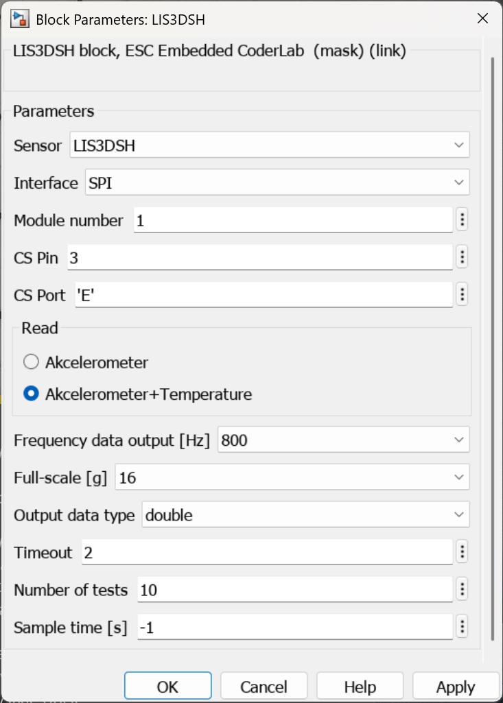
| Parameter | Description |
|---|---|
| Sensor | Switch between available sensors |
| Interface | Switch between interfaces:I2C - select I2C interfaceSPI - select SPI interface |
| Module number | Number of I2C/SPI module used in the model |
| CS Pin | Specified pin for the chip select line |
| CS Port | Specified port for the chip select line |
| Read | Specifies what data is being read:Akcelerometer - read accelerometer dataAkclereometer + Temperature - read accelerometer and temperature data |
| Frequency data output | LIS3 data output rate in Hz |
| Full-scale [gauss] | Full-scale configuration |
| Output data type | Specified type of reading data:int16 - integer 16-bitsingle - single-precision floating-pointdouble - double-precision floating-point |
| Timeout | Timeout duration |
| Number of tests | Specified maximum number of tries to initialize the sensor |
| Sample time | Period of function refreshing |
CubeMX Configuration for a Given MCU
H7
Dependent on the interface
I2C interface
| Nb. | Name | Path | Setting | Description | Screenshot |
|---|---|---|---|---|---|
| 1 | I2C Mode | Pinout & Configuration > Connectivity > I2C* > Mode | I2C | I2C Mode should be set to I2C |  |
| 2 | I2C Clock Speed | Pinout & Configuration > Connectivity > I2C* > Parameter Settings > Timing configuration > I2C Speed Mode | Fast Mode | I2C Clock Speed can be set maximum as 400 kHz in Fast Mode |  |
I2C* - simbol * is a number of the I2C module used in the model, e.g. I2C1, I2C2, etc.
SPI interface
| Nb. | Name | Path | Setting | Description | Screenshot |
|---|---|---|---|---|---|
| 1 | SPI Mode | Pinout & Configuration > Connectivity > SPI* > Mode | Full-Duplex Master | SPI Mode should be set to Full-Duplex Master |  |
| 2 | SPI Baud Rate | Pinout & Configuration > Connectivity > SPI* > Parameter Settings > Mode | Full-Duplex Master | SPI Baud Rate can be set maximum as 10 MBits/s. This setting depends on the SPI clock and Prescaler |  |
I2C* - simbol * is a number of the SPI module used in the model, e.g. I2C1, I2C2, etc.