TIM PWM Generation Block Description
This block enables PWM signal generation using timers in STM microcontrollers.
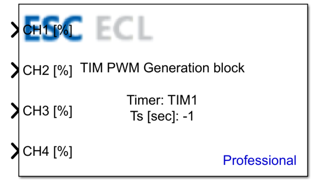
Table of Contents
Inputs
| Input Name | Type | Description |
|---|---|---|
| CH* [%] | uint8 | The duty cycle percentage of the PWM signal for the given channel. The value must be within the range of 0 to 100, where 0 represents no signal output and 100 represents full PWM signal duty cycle. |
| Period [sec] | uint16 | Conditional input The PWM signal period value in microseconds. The availability of this input port depends on the Enable input period parameter. |
CH* [%] – PWM channel inputs, where * denotes the specific channel number (e.g., CH1 [%], CH2 [%], etc.).
Outputs
This block has no outputs.
Block Parameters
| Parameter | Description |
|---|---|
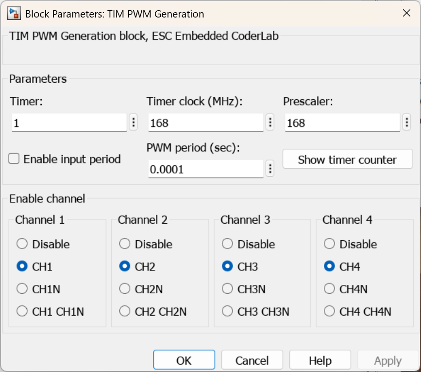
| Timer | The timer number designated to generate hardware interrupts. |
| Timer clock (MHz) | The core operational frequency of the timer clock in MHz. |
| Prescaler | The hardware prescaler value for the timer. |
| Enable input period | Enables an input port that allows dynamically setting the PWM signal period. |
| PWM Period (sec) | Conditional Parameter The fixed period value for the timer counter. This parameter is only accessible when the Enable input period option is disabled. |
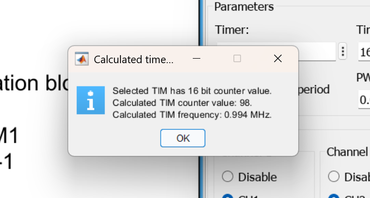
| Show timer counter | Conditional Parameter Displays comprehensive internal details of the timer counter registers. This parameter is only accessible when the Enable input period option is disabled. |
| Enable channel | Configures the operational mode for individual PWM channels:Disable – channel is turned off.CH* – channel is enabled with standard/positive polarity.CH*N – channel is enabled with complementary/negative polarity.CH* CH*N – channel is enabled with both standard and complementary outputs active. |
CubeMX Configuration for a Given MCU Model
H7
| No. | Name | Path | Setting | Description | Screenshot |
|---|---|---|---|---|---|
| 1 | Clock Source | Pinout & Configuration > TIM* > Mode > Clock Source | Internal Clock | Selects the active operational clock source for the timer. | 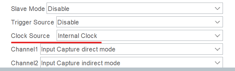 |
| 2 | Global interrupt / Update interrupt | Pinout & Configuration > TIM* > NVIC Settings > Global interrupt / Update interrupt | Enabled | Enables hardware interrupts for the timer. Depending on the timer type, a Global or Update interrupt channel is available; one of these options must be enabled. | 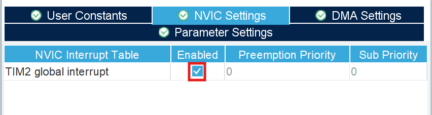 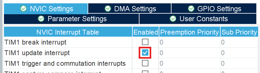 |
| 3 | Channel* Configuration | Pinout & Configuration > TIM* > Mode > Channel* | CH*CH*NCH* CH*N | Selects the generation method of the PWM signal for the specific channel. This setting must explicitly match the selection made in the Enable channel block parameter. | 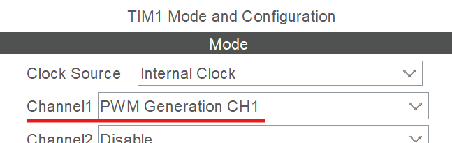 |
CH* – the PWM channel identifier where * denotes the channel index number (e.g., CH1, CH2, etc.).
See Also
Last updated on